User's Guide and General Information
DCFEB Optical test
- Testing Manual, 13 August 2018
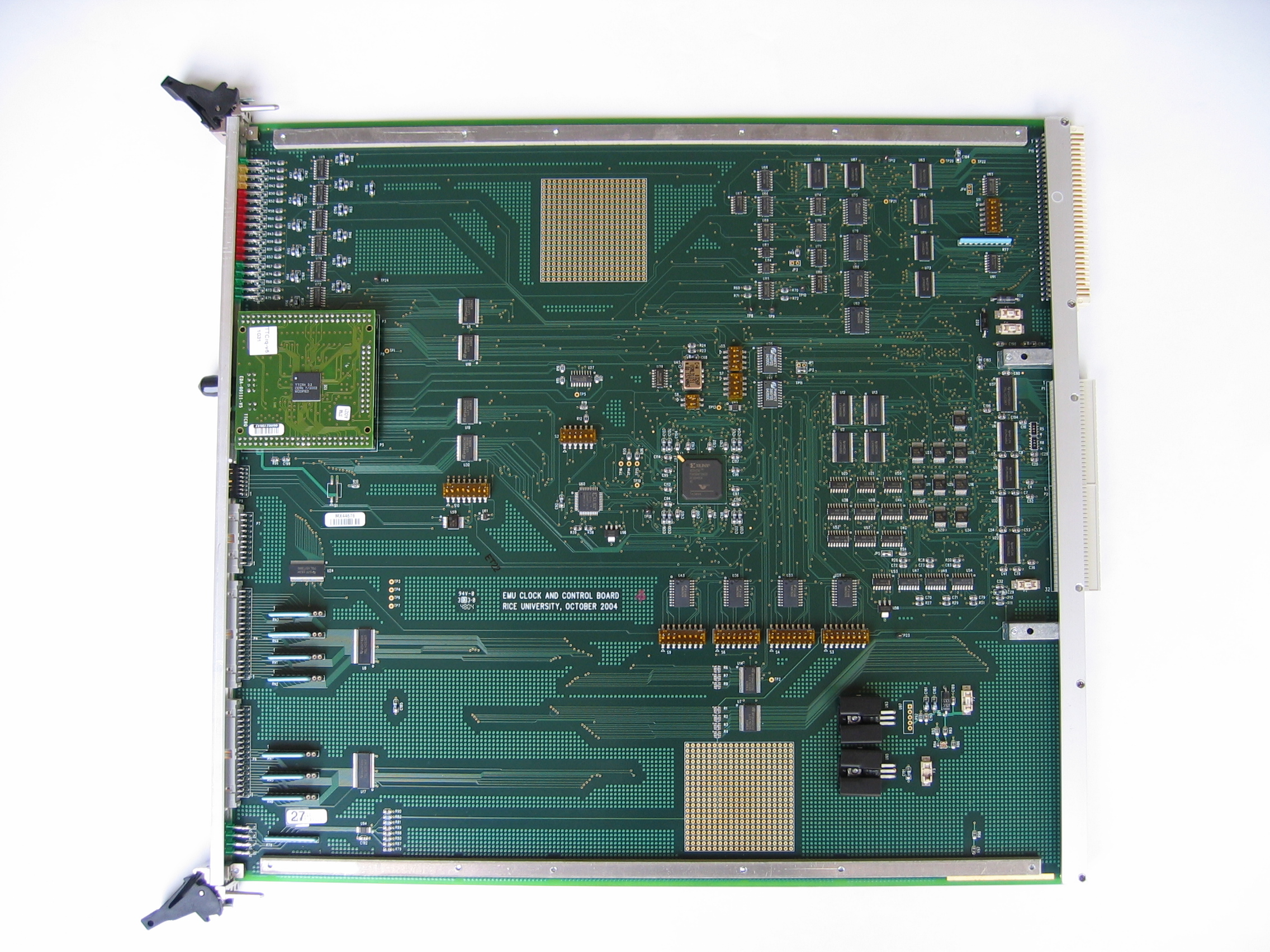
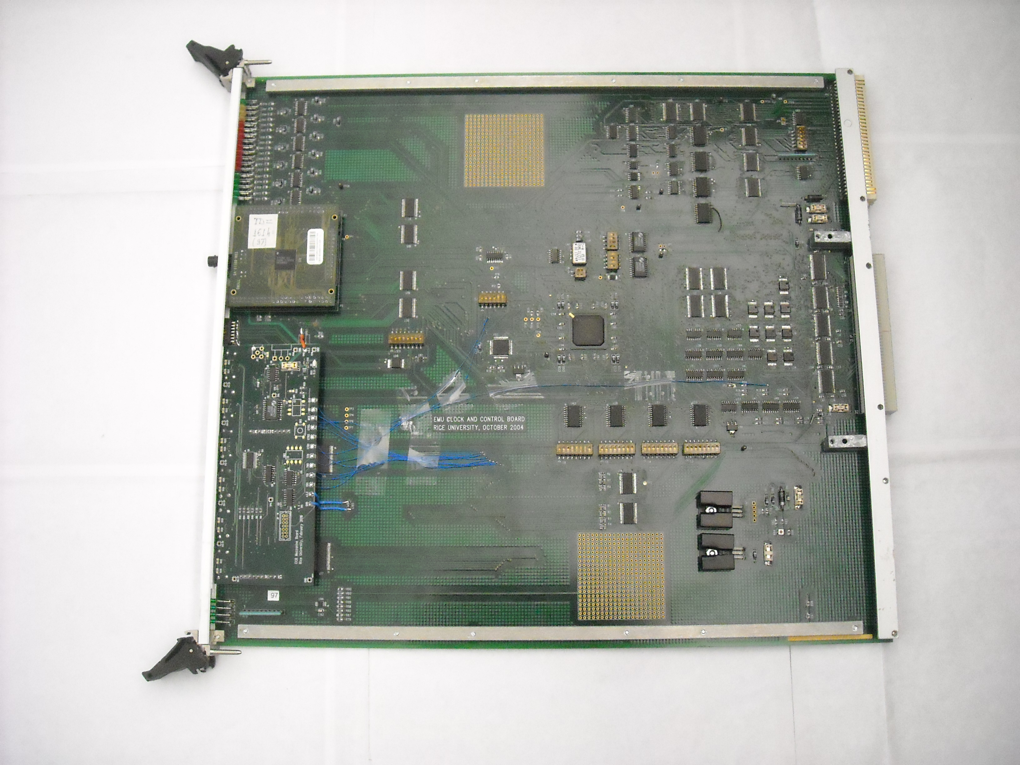
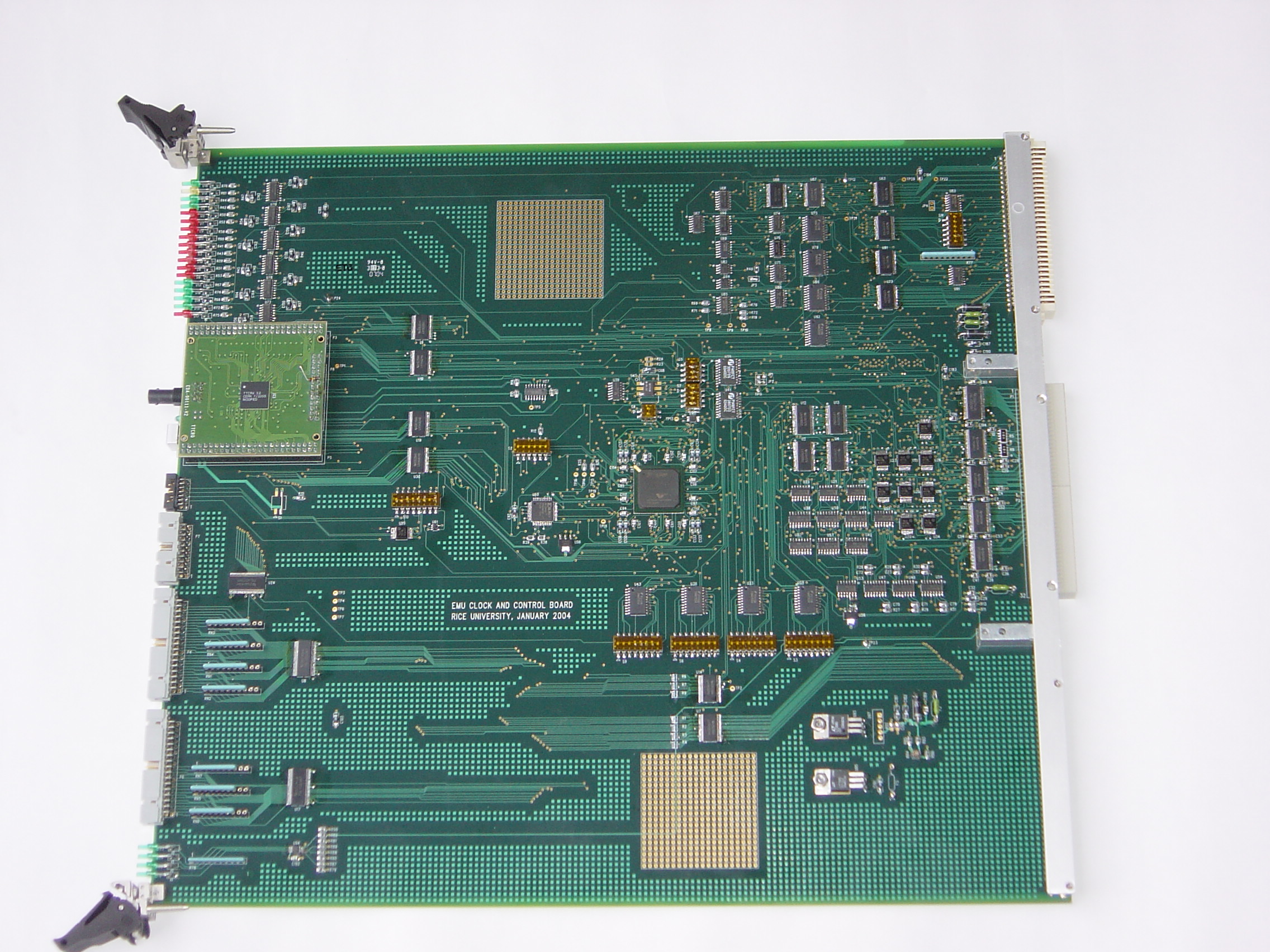
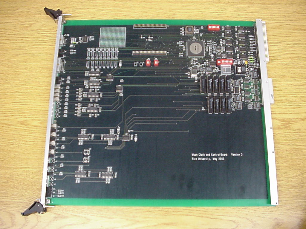
Clock and Control Board
CCB'2004 for the EMU Peripheral and Track Finder Electronics, Production Version (October 2004)
Board status and
location
- CCB'2004 Specification. Version 3.4.5, 10/21/2010.
Corresponds to firmware of 10/21/2010.
- Configuration files .mcs and
.svf for the XC18V02VQ44 EPROM.
Version 09/15/2017 (232Fhex)
for CCBs at p.5. Modified version of 03/25/2011 firmware with the possibility to mask out Hard Resets to individual
boards in the peripheral crate. CSRB4[0]=0/1 enables/disables Hard Resets to ALCTs. CSRB4[1]=0/1 enables/disables Hard
Resets to TMBs. CSRB4[2]=0/1 enables/disables Hard Resets to DMBs. CSRB4[3]=0/1 enables/disables Hard Reset to MPC.
Default setting for these bits after power cycle is "0" (Hard Resets enabled to all target boards).
The CCB must be in the "FPGA" mode (CSRA1[0]=0 and CSRB1[0]=0) to utilize these options.
Archived version of this project is here.
- Configuration files .mcs and
.svf for the XC18V02VQ44 EPROM.
Version 02/25/2016 (205ahex)
for the CCB at GIF++. Modified version of 03/25/2011 firmware. The delay between two consecutive L1A requests
(to the peripheral backplane and front panel connector) is programmable by CSRB4(15:0): bit[0]=25ns, bit[1]=50ns, bit[2]=100ns,
bit[15]=800us; max delay = 1.6ms. The block diagram of possible L1A_Request sources is here.
Archived version is here.
- Configuration files .mcs and
.svf for the XC18V02VQ44 EPROM.
Version 01/15/2016 (202Fhex)
for the CSCTF crate. Simplified version of 03/25/2011 firmware. Only one source of L1A_request in CSRB1 is
uncondionally enabled (from the TMB/SP). Bits 2-7, 11-15 in CSRB1 are not used. Archived version is here.
- Configuration files .mcs and
.svf for the XC18V02VQ44 EPROM.
Version 03/25/2011 (1679hex)
(same as version 10/21/2010, but compiled with the ISE 10.1.3). Archived version is here.
- Configuration files .mcs and
.svf for the XC18V02VQ44 EPROM.
Version 03/09/2015 (1E69hex)
for OSU tests only. Same as version 03/25/2011 with two modifications: the L1A delay is now increased from 8 to 10 bits CSRB5[9:0]
and the ALCT/CLCT delay is reduced from 8 to 6 bits CSRB5[15:10]; compiled with the ISE 10.1.3.
- Configuration files .mcs and
.svf for the XC18V02VQ44 EPROM.
Version 10/21/2010 (1555hex)
(same as version 08/21/2008 with two modifications: CSRB20 was removed;
CSRB19 expanded to 32 bits; compiled with the ISE 6.2.03).
- FPGA Release Notes Version 10/21/2010
- CCB FPGA Description
- CCB'2004 Specification. Version 3.4.4, 04/30/2009.
Corresponds to firmware of 08/21/2008.
- CCB'2004 Specification. Version 3.4.2, 04/02/2008. Corresponds to firmware of 02/15/2008.
- Configuration files .mcs and
.svf for the XC18V02VQ44 EPROM.
Version 02/15/2008 (104Fhex)
(same as version 09/10/2007 with the CSRB19 (TTC_BRCSTSTR1_counter), CSRB20 (TTC_BRCSTSTR2_counter) and
CSRB21 (TTC_DATSTR_counter) addeed).
- FPGA Release Notes Version 02/15/2008
- CCB FPGA Description
- CCB'2004 Specification. Version 3.4, 06/27/2007. Corresponds to firmware of 09/01/2006, 03/05/2007 and 09/10/2007.
- Configuration files .mcs and
.svf for the XC18V02VQ44 EPROM.
Version 09/10/2007
(same as version 03/05/2007; L1A latency=2BX in both "discrete logic" and "FPGA" modes.
Previously latency was 2BX in "discrete logic" and 3BX in "FPGA" modes).
- Configuration files .mcs and
.svf for the XC18V02VQ44 EPROM.
Version 03/05/2007
(same as version 09/01/2006 with fixed logic
to generate the L1A on asynch_pulse).
- Configuration files .mcs and
.svf for the XC18V02VQ44 EPROM. Version 09/01/2006
(Added feature: DMB_cfeb_calibrate[2..0] pulses may produce an L1ACC to custom backplane).
- CCB'2004 Specification. Version 3.2, 07/28/2006. Corresponds to firmware of 02/03/2006.
- Configuration files .mcs and
.svf for the XC18V02VQ44 EPROM. Version 02/03/2006
(L1ACC can be generated from the rising edge of TMB_L1A_REQ or TMB_L1A_REL signals instead of falling edge
in the previous versions of firmware).
- CCB'2004 Specification. Version 3.1, 04/12/2005. Corresponds to firmware of 01/15/2005.
- Configuration files .mcs and
.svf for the XC18V02VQ44 EPROM. Version 01/17/2005.
-
TTCrq mezzanine specification and schematic. Version 1.5, November 2004
-
I2C Bus Specification. Version 2.1, January 2000.
- CCB'2004 Schematic (pdf files)
- CCB2004 production baseboard PCB fabrication files
- CCB2004 Xilinx project
(zip) . Version 02/15/2008 (open with Xilinx ISE 6.2.03).
- CCB2004 Xilinx project
(zip) . Version 08/21/2008 (open with Xilinx ISE 6.2.03).
- CCB2004 EPROM erase
svf file.
CCB Mezzanine board for GEM electronics, March 2016
- Draft Specification. Version 04/29/2016
- mcs configuration file for the CCB XC18V02 EPROM. Version 04/29/2016 (default MUX=1)
- svf configuration file for the CCB XC18V02 EPROM. Version 04/29/2016 (default MUX=1)
- Schematics of the mezzanine board. Version 02/02/2016
-
Archived version is here.
- Test mcs file for the OH v.2b XCF128X PROM. Version 04/29/2016
- Test svf file for the OH v.2b XCF128X PROM. Version 05/02/2016
CCB'2004 for the EMU Peripheral and Track Finder Electronics, Preproduction Version (January 2004)
- CCB'2004 Specification. Version 2.0, 12/24/2004
- Configuration files .mcs and
.svf for the XC18V02VQ44 EPROM. Version 12/24/2004.
- Configuration files .mcs and
.svf for the XC18V02VQ44 EPROM. Version 10/13/2004 (added:
expanded to 500 ns Hard_reset, CSRB18, "Reset TTCrx" command).
- Configuration files .mcs and
.svf for the XC18V02VQ44 EPROM. Version 03/25/2004.
- CCB'2004 Schematic (pdf files)
CCB'2001 for the EMU Peripheral and Track Finder Electronics
- CCB'2001 Specification. Version 2.2, 08/04/2006
- CCB'2001 .pof file for the EPC2 EPROM. Version 12/09/2002
- CCB'2001 .pof file for the EPC2 EPROM. Version 02/01/2003
- CCB Schematic (pdf files)
- TTCrx Manual. Version 3.11, December 2005
- QPLL Manual. Version 1.3, 26 February 2009
- QPLL Locking Mechanism. A Brief Note, 12 February 2009
- TTCrq Manual, Version 1.5, November 2004.
- TTCrq Mezzanine Board Schematic, 30 November 2004
- TTCvi-MkII Manual. Rev.1.6, May 2000.
- TTCvx Technical Description and Users Manual. May 21, 1999.
- TTCmi Machine Interface. Users Manual, Rev. 1.3
- Clock Propagation Delays over EMU Peripheral Backplane.
Version 05/09/2002
- Jitter Measurements with a TTCrx ASIC, 03/18/2002
- Irradiation Test of the CCB, 02/27/2002
- CCB'2001 Block Diagram. Version 01/16/2002
-
CCB'2001 Backplane connector drawing (.dxf file)
- Pin assignment for the boards in the EMU peripheral crate.
A.Madorsky, 3 March 2001.
-
CSC Track Finder Crate Specification. A.Madorsky, 12 December 2002.
- General Information on TTC System (CERN RD12)
-
CMS L1 Trigger Control System. CMS Note 2002/033
-
Summary of Timing and Control Signals. Working document Version 24.10.2000
-
B.Taylor. Timing Distribution at the LHC. Presented at the
8th Workshop on Electronics for LHC Experiments, Colmar, France, 9-13 September 2002
-
Philips PCF8584 I2C Bus Controller. Specification and programming tips
- Example of TTCrx programming using PCF8584 (.txt file)
- Example of IDCODE/USERCODE read procedure via JTAG
from XC2V250 FPGA or XC18V02 EPROM (.txt file)
- Example of IDCODE/USERCODE read procedure via JTAG
from XC2V4000 FPGA on TMB2005 mezzanine board (.txt file)
Software to run
TTCvi and TTCvx modules under VME control
Developed by Karol Bunkowski
of Warsaw University. Tested in March'2002 at Rice University with the Model 617
and Model 618 PCI-to-VME Bus Adapters
from SBS Technologies and CCB'2001 for the
EMU Peripheral Electronics.
- TTCviCPP.zip contains C++ source files with TTCvi class (TTCviN.h file),
which provides all functions needed to control TTCvi board and connected
to it TTCrx boards. It also contains VME classes that are used to talk to
VME via Bit3 interface (Bit 3 Model 983 support software)
(files TVMEInterface.h and TVMEWinBit3.h).
- ConsoleTTCvi.zip contains the Microsoft Visual C++ project with the consol
application that sets TTCvi for sending commands required by CCB.
It may be treated as an example of using TTCvi class. With some small
changes it should be possible to compile the files with any other C++ compilator.
- WinTTCvi.zip contains Windows GUI application (TTCContr.exe) that gives
full control over TTCvi board.
CCB'99 for the EMU Peripheral Electronics
This is a first prototype of the CCB designed in 1999 for communication
with the TMB'99, CLCT'99 and ALCT'99 prototype boards.
CCB'2000 for the Track Finder crate
This is the first prototype of the CCB for the CSC Track Finder crate.
Three boards were built in summer 2000 and used at the University of Florida,
UCLA and Rice for joint test of the Sector Receiver and Sector Processor
modules. Will be replaced by the CCB'2001.
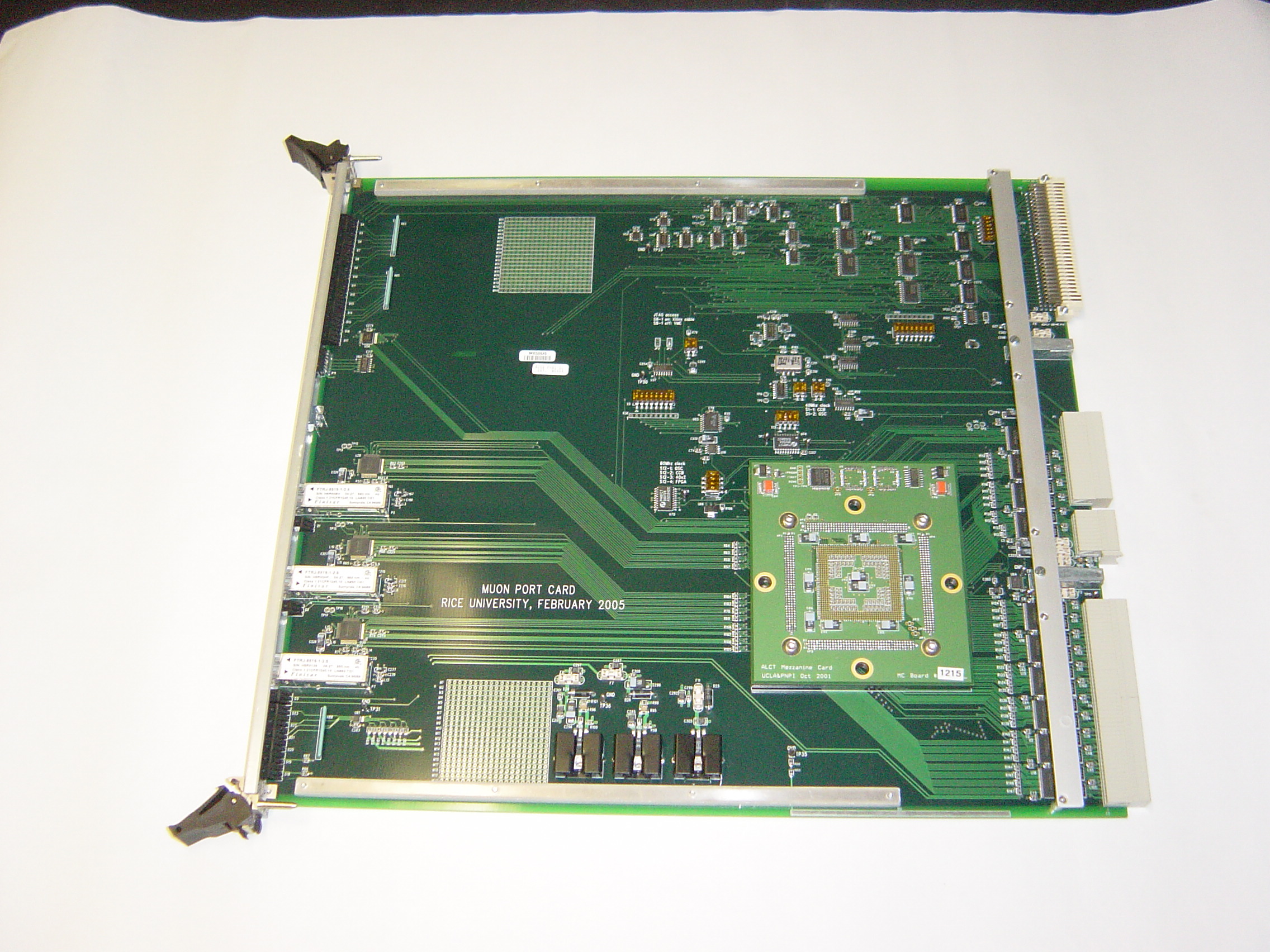
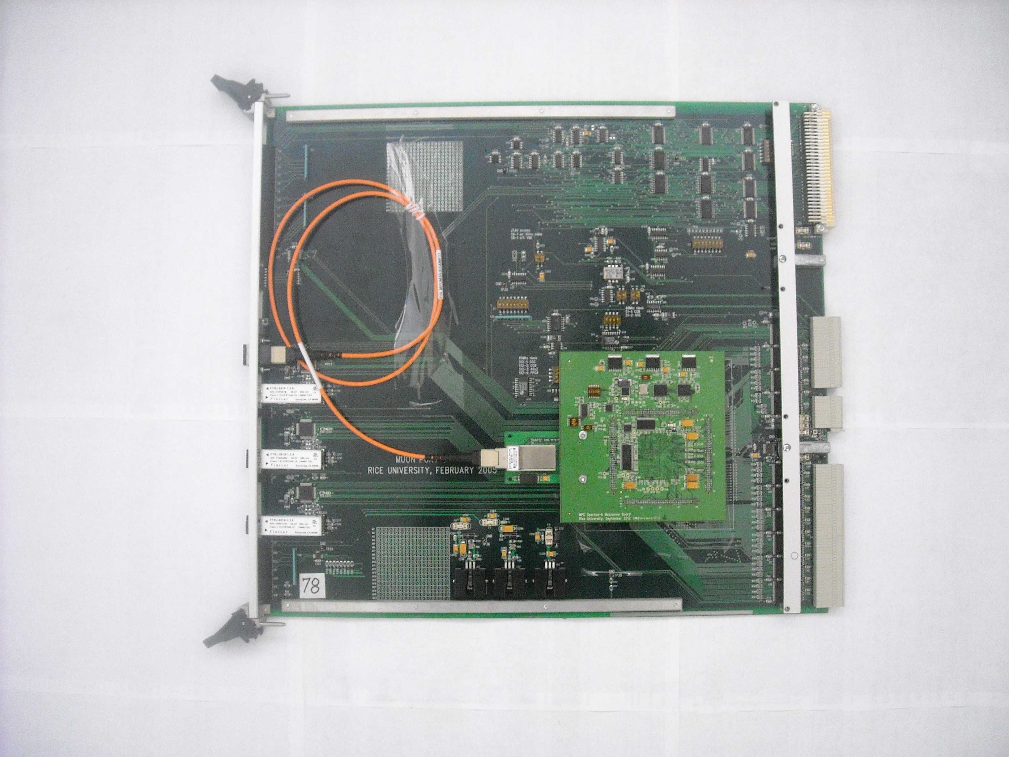
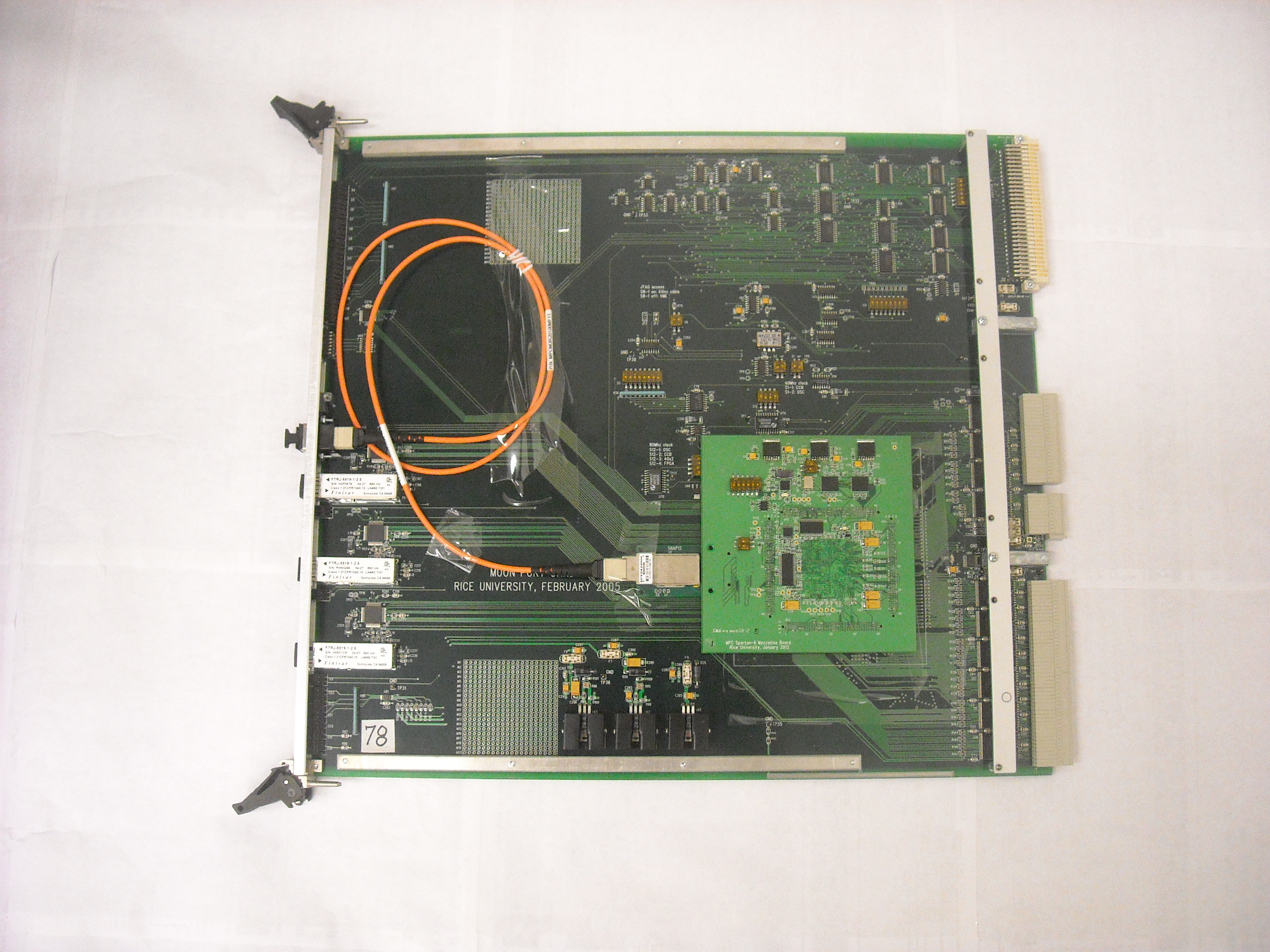
Muon Port Card
The MPC resides in the middle of the peripheral EMU crate and receives
trigger primitives from 9 or 8 Trigger Motherboards (designed at UCLA).
MPC'2002 selects three best patterns out of 18 (or 16) and transmits them
over three optical links to new combined Sector Receiver/Sector Processor
board (designed at the University of Florida).
MPC2004 for the EMU Peripheral Electronics (Production Version, February 2005)
Board status and
location
- Firmware revision 05/10/2010
(Based on revision 10/08/2008, but can disable specific TMB inputs by default (after power cycyling
and hard reset). In the 10/08/2008 revision all the TMB inputs are enabled
by default. Version mi (i=1..9) masks out one TMBi in the peripheral crate. CSR7 and CSR8 are not needed.
-
Configuration mcs and svf files to mask off the TMB1.
-
Configuration mcs and svf files to mask off the TMB2.
-
Configuration mcs and svf files to mask off the TMB3.
-
Configuration mcs and svf files to mask off the TMB4.
-
Configuration mcs and svf files to mask off the TMB5.
-
Configuration mcs and svf files to mask off the TMB6.
-
Configuration mcs and svf files to mask off the TMB7.
-
Configuration mcs and svf files to mask off the TMB8.
-
Configuration mcs and svf files to mask off the TMB9.
- MPC'2004 Specification. Version 10/08/2008
(Board_ID[5..0] and Link_ID[1..0] added,
CSR7 and CSR8 added to mask/unmask individually any LCT from any TMB, sorting scheme was changed to allow
zero-quality LCT's with vpf=1 to participate in sorting. New for this version: when the LCT0 and LCT1 from the
same TMB have equal "quality"
values, the LCT0 will have the precedence over LCT1. All previous versions of firmware implement the opposite
scheme, when the LCT1 had a precedence over LCT0)
-
Configuration mcs file for the XC18V04 EPROM. Version 03/25/2011
(same as version 10/08/2008, but compiled with the ISE 10.1.3)
-
Configuration svf file for the XC18V04 EPROM. Version 03/25/2011
(same as version 10/08/2008, but compiled with the ISE 10.1.3)
-
Configuration mcs file for the XC18V04 EPROM. Version 10/08/2008 (compiled with the ISE 6.2.03).
-
Configuration svf file for the XC18V04 EPROM. Version 10/08/2008 (compiled with the ISE 6.2.03).
- FPGA Release Notes Version 10/08/2008
- MPC FPGA Description
- PCB fabrication files Version 02/28/2005
- PCB assembly files Version 02/28/2005
- MPC'2004 Specification. Version 02/12/2007
(Board_ID[5..0] and Link_ID[1..0] added,
CSR7 and CSR8 added to mask/unmask individually any LCT from any TMB, sorting scheme was changed to allow
zero-quality LCT's with vpf=1 to participate in sorting)
-
Configuration mcs file for the XC18V04 EPROM. Version 10/27/2006
(including Board_ID[5..0] and Link_ID[1..0], CSR7 and CSR8, zero-quality LCT's with vpf=1 participate in sorting)
-
Configuration svf file for the XC18V04 EPROM.
Version 10/27/2006 includes the Board_ID[5..0] + Link_ID[1..0], CSR7 and CSR8, zero-quality LCT's with vpf=1
participate in sorting.
- MPC'2004 Specification. Version 10/26/2006 (Board_ID[5..0] and Link_ID[1..0] added,
CSR7 and CSR8 added to mask/unmask individually any LCT from any TMB)
- Configuration mcs file for the XC18V04 EPROM. Version 10/26/2006
(including Board_ID[5..0] and Link_ID[1..0], CSR7 and CSR8, zero-quality LCT's with vpf=1 do not participate in sorting)
- Configuration svf file for the XC18V04 EPROM.
Version 10/26/2006 (including Board_ID[5..0] and Link_ID[1..0], CSR7 and CSR8,
zero-quality LCT's with vpf=1 do not participate in sorting).
- MPC'2004 Specification. Version 04/26/2006 (Board_ID[5..0] and Link_ID[1..0] added)
- Configuration mcs file for the XC18V04 EPROM. Version 04/26/2006
(including Board_ID[5..0] and Link_ID[1..0])
- Configuration svf file for the XC18V04 EPROM.
Version 04/26/2006 (including Board_ID[5..0] and Link_ID[1..0]).
- MPC'2004 Specification. Version 11/24/2005 (Including transparent BC0)
- Configuration mcs file for the XC18V04 EPROM. Version 11/24/2005
(Including transparent BC0)
- Configuration svf file for the XC18V04 EPROM. Version 11/24/2005
(Including transparent BC0)
- Configuration svf file to program XC18V04 EPROM. Version 10/20/2005
- Configuration svf file to verify XC18V04 EPROM. Version 10/20/2005
- Configuration mcs file for the XC18V04 EPROM. Version 04/23/2005
- Configuration svf file to program XC18V04 EPROM. Version 04/23/2005
- Configuration svf file to verify XC18V04 EPROM. Version 04/23/2005
- Configuration svf file to erase XC18V04 EPROM. Version 04/23/2005
- MPC2004 .ucf file
- Eye diagram and jitter measurements at the SP input
(differential outputs DOUTTXP/DOUTTXN of the TLK2501 receiver; 100 m multimode
fiber; 1.6Gbps rate)
- MPC2004 Schematic (pdf files)
- MPC2004 special project with the LFSR-based 15-bit PRBS generators for the optical links.
Identical PRBS generators for all three links. PRBS generators run continuously after power cycling.
Links need to be initialized by sending the L1Reset command.
The generators are reset by the BC0 pulse which is transmitted as a 16th bit
in the datastream from the MPC to SP. Interface to TMBs, sorter unit, FIFO_A and FIFO_B are not available.
- mcs file for XC18V04 EPROM
- svf file for the XC18V04 EPROM
- Simplified block diagram of the transmitter and receiver PRBS logic.
BC0 in the transmitter part here is a 12.5 ns pulse derived from the 25 ns BC0 TTC command.
- Firmware for the MPC2004, version 05/20/2008. Same as 10/27/2006, plus 16-bit L1Reset counter
added. Available for read (base address + B4). Reset on "FPGA Soft Reset command.
- Configuration mcs file for the XC18V04 EPROM. Version 05/20/2008
- Configuration svf file for the XC18V04 EPROM. Version 05/20/2008.
-
MPC-to-SP Synchronization Procedure (L.Uvarov)
- MPC2004 Xilinx project
(zip) . Version 10/27/2006 (open with Xilinx ISE 6.2.03).
- MPC2004 Xilinx project
(zip) . Version 10/08/2008 (open with Xilinx ISE 6.2.03).
- Example of IDCODE/USERCODE read procedure via JTAG
from XC18V04 EPROM (.txt file)
- Simplified TMB2005-to-MPC2004 data transmission test code (.txt file)
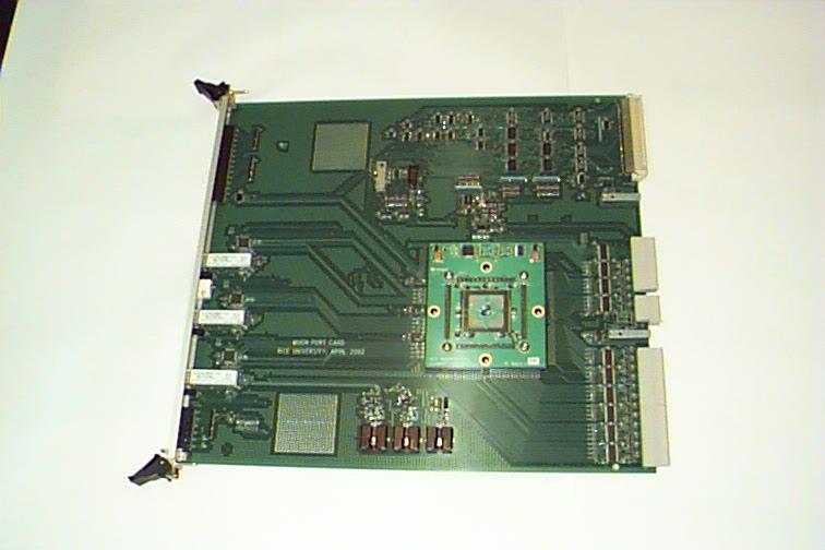
MPC'2002 for the EMU Peripheral Electronics (Initial Prototype, April 2002)
MPC'2000 for the EMU Peripheral Electronics
This is the first prototype of MPC designed in 2000. The board is able to
receive up to six trigger primitives from three Trigger Motherboards TMB'99,
select three best and transmit them to Sector Receiver prototype designed
at UCLA in 2000. The boards were used at the University of Florida for joint
tests with a prototypes of Sector Receiver and Sector Processor modules.
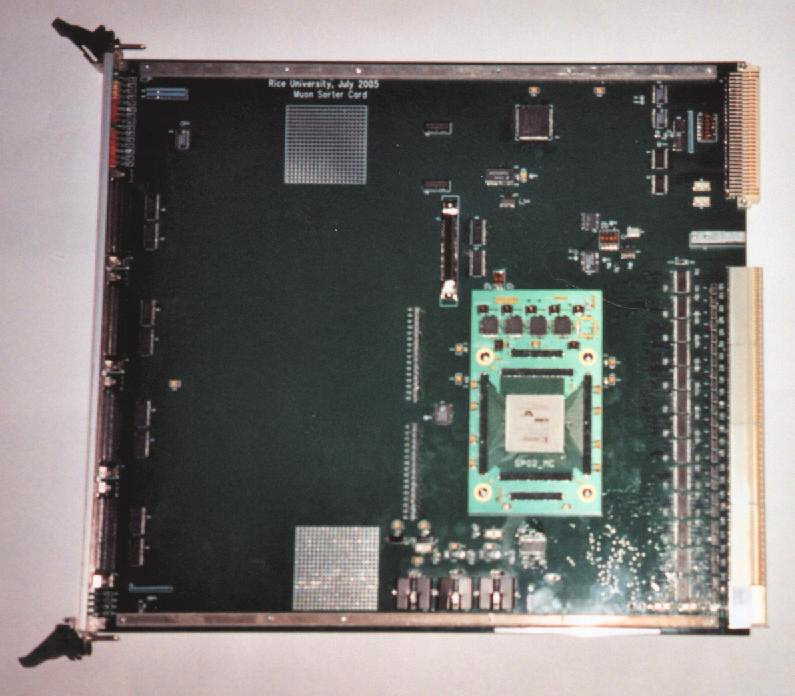
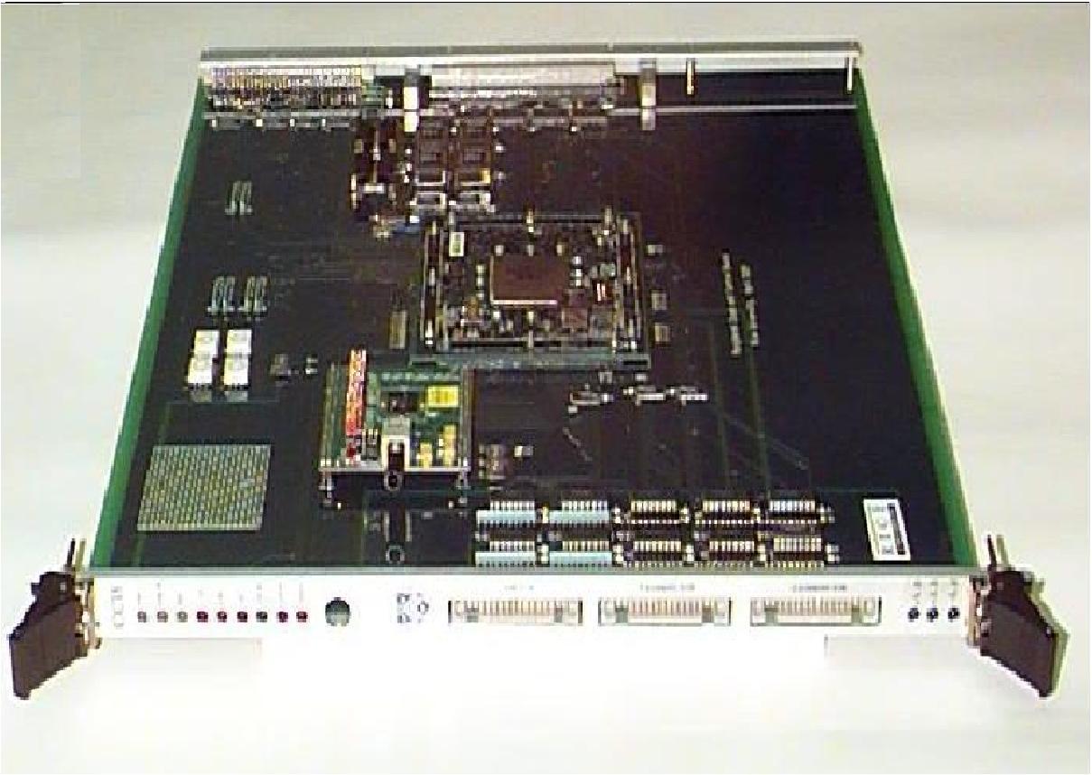
Muon Sorter
Muon Sorter receives up to 36 reconstructed muon primitives from
12 Sector Processors, selects the four best and transmits them to the Global Muon
Trigger crate for further processing. Muon Sorter resides in the middle
of the Track Finder crate and communicates with the Clock and Control Board (CCB) and Sector Processors
over custom backplane.
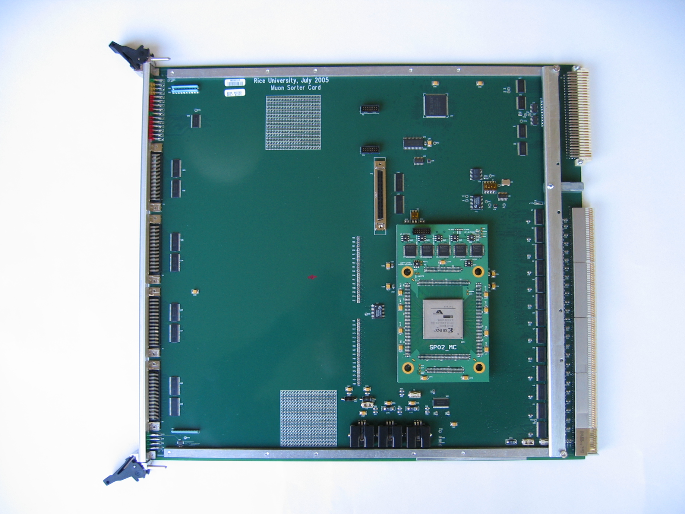
MS2005 (Production Version, July 2005)
Board Status (Location, Firmware, Hardware,
Mezzanines)
-
Virtex-5 Mezzanine card for the MS2005 baseboard. Draft Specification. Version 1.0, 04/10/2015
-
MS2005 Specification. Version 1.5, 09/07/2009
- Configuration files (.mcs) for XC18V04
EPROM1,
EPROM2,
EPROM3,
EPROM4,
version 03/25/2011 (same as version 09/07/2009, but compiled with the ISE 10.1.3).
- Configuration
svf file for all four XC18V04 EPROMs, version 03/25/2011
(same as version 09/07/2009, but compiled with the ISE 10.1.3).
- Configuration files (.mcs) for XC18V04
EPROM1,
EPROM2,
EPROM3,
EPROM4,
version 09/07/2009 (based on version of 03/31/2009 with four "rate" counters added, compiled with the ISE 6.2.03).
- Configuration
svf file for all four XC18V04 EPROMs, version 09/07/2009 (compiled with the ISE 6.2.03).
- Configuration files (.mcs) for XC18V04
EPROM1,
EPROM2,
EPROM3,
EPROM4,
Trial version (based on version of 09/07/2009, compiled with the ISE 6.2.03).
- Configuration
svf file for all four XC18V04 EPROMs, DATE_ID=169Dh (compiled with the ISE 6.2.03).
- Configuration
jed file for the Xilinx XCR3128XL PLD, Version 17 August 2005.
- MS2005 Specification. Version 1.4, 03/09/2009
- Configuration files (.mcs) for XC18V04
EPROM1,
EPROM2,
EPROM3,
EPROM4,
version 03/31/2009 (parity calculation for the GMT was changed from XNOR[29:0] to XOR[29:0];
trigger start/stop commands are not needed any more to send the BXN[2:0] bits from the internal
bunch crossing counter to the GMT; bit CSR6[15] was specified to allow data capture from
sorting unit to FIFO_D).
- Configuration
svf file for all four XC18V04 EPROMs, version 03/31/2009.
- FPGA Release Notes Version 03/31/2009
- PLD Release Notes Version 08/16/2005
- MS FPGA Description
- MS PLD Description
- MS2005 Specification. Version 1.3, 06/26/2007
- Configuration files (.mcs) for XC18V04
EPROM1,
EPROM2,
EPROM3,
EPROM4,
version 06/26/2007 (same functionality as version 07/31/2006, but more flexible
control of the output RAM).
- Configuration
svf file for all four XC18V04 EPROMs, version 06/26/2007.
- MS2005 Specification. Version 1.2, 03/01/2007
- Configuration files (.mcs) for XC18V04
EPROM1,
EPROM2,
EPROM3,
EPROM4,
version 07/31/2006 (same functionality as version 11/11/2005, but reduced latency = 125 ns)
- Configuration files (.mcs) for XC18V04
EPROM1,
EPROM2,
EPROM3,
EPROM4,
version 11/11/2005 (latency = 150 ns)
- Erase EPROM's
svf file for all four XC18V04 EPROMs, version 11/11/2005
- Configuration
svf file for all four XC18V04 EPROMs, version 07/31/2006
- Configuration
svf file for all four XC18V04 EPROMs, version 11/11/2005
- Configuration
svf file for all four XC18V04 EPROMs, version 08/16/2005
- Configuration
evf file for all four XC18V04 EPROMs, version 08/16/2005
- Programming jed file for Xilinx XCR3128XL PLD, version 08/17/2005
- Programming jed file for Xilinx XCR3128XL PLD, version 07/29/2003
- Programming jed file for Xilinx XCR3128XL PLD, version 11/05/2003
-
MS2005 LUT dump (version October 2009)
-
MS2005 LUT dump (version October 2007)
MS2005 Schematic (pdf files)
Specification of the MS-to-GMT non-halogen copper cable
MS2005 Xilinx FPGA project
(zip) . Version 09/07/2009 (open with Xilinx ISE 6.2.03).
MS2005 Xilinx FPGA project
(zip) . Version 03/31/2009 (open with Xilinx ISE 6.2.03).
MS2005 Xilinx FPGA project
(zip) . Version 06/26/2007 (open with Xilinx ISE 6.2.03).
MS2005 Xilinx PLD project
(zip) . Version 08/16/2005 (open with Xilinx ISE 6.2.03).
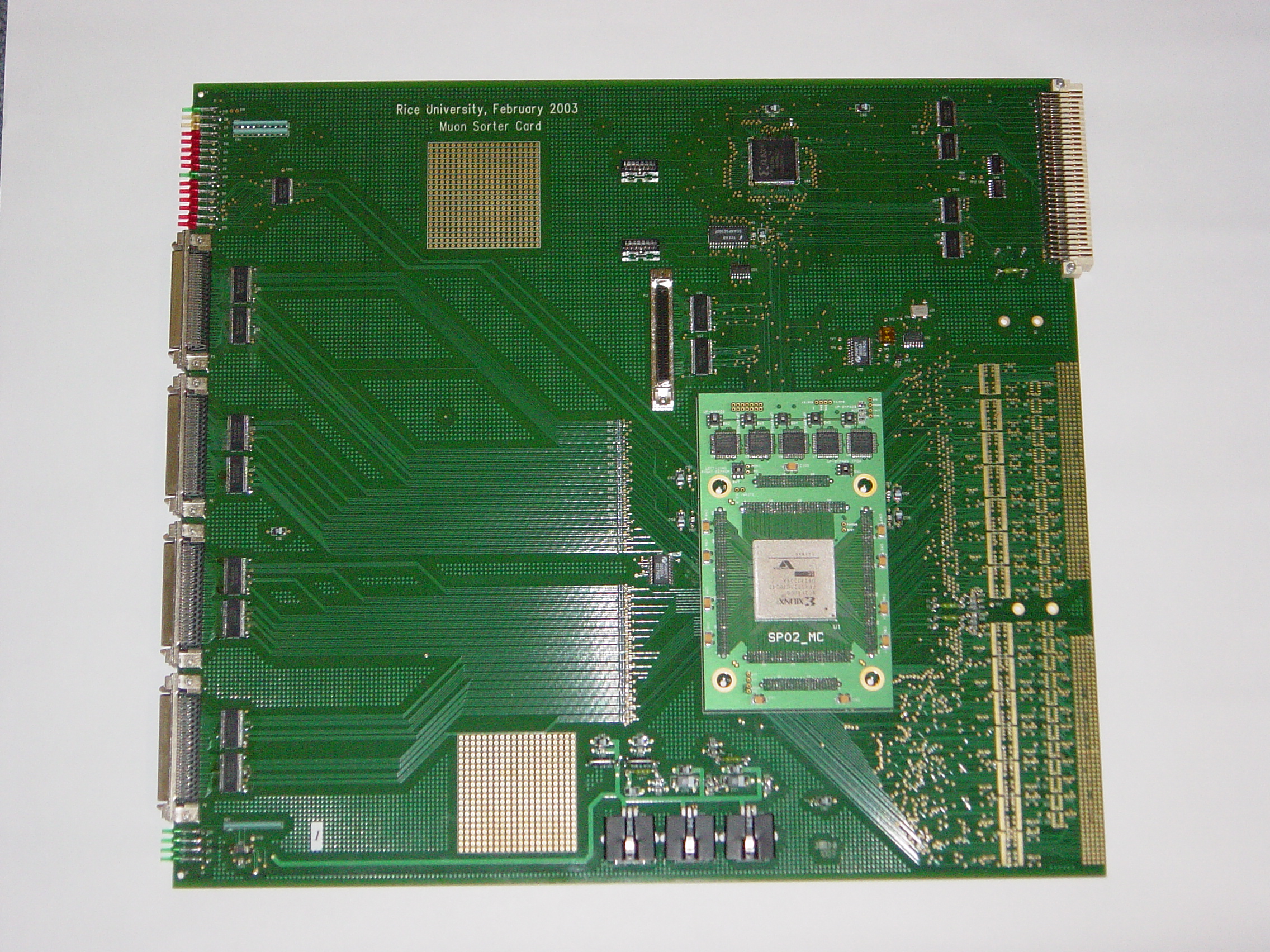
MS2003 (First Version, February 2003)
- Muon Sorter Specification. Version 2.1, 11/19/2004
(with four output RAM buffers)
- Muon Sorter Specification. Version 2.0, 05/04/2004
- Configuration files (.mcs) for XC18V04
EPROM1,
EPROM2,
EPROM3,
EPROM4,
version 06/16/2004 (modified data format to GMT, modified "winner" bits to SP)
- Configuration files (.svf) for XC18V04
all 4 EPROM's,
EPROM1,
EPROM2,
EPROM3,
EPROM4,
version 06/16/2004
- Configuration files (.mcs) for XC18V04
EPROM1,
EPROM2,
EPROM3,
EPROM4,
version 12/10/2003
MS Schematic (pdf files)
EPROM Configuration file (.evf)
for SCANPSC100F controller, version 12/10/2003
Configuration file (.jed) for XCR3128XL PLD, version 11/05/2003
National SCANPSC100FSC JTAG Controller
Mechanical Drawing of
the backplane connectors, 12/06/2002
CSC Track Finder Crate Specification. December 2002.
Specification if the Interface Between the Regional
Muon Triggers and the Global Muon Trigger. CMS Internal Note IN 2004/022 Version 1.00. June 8, 2004
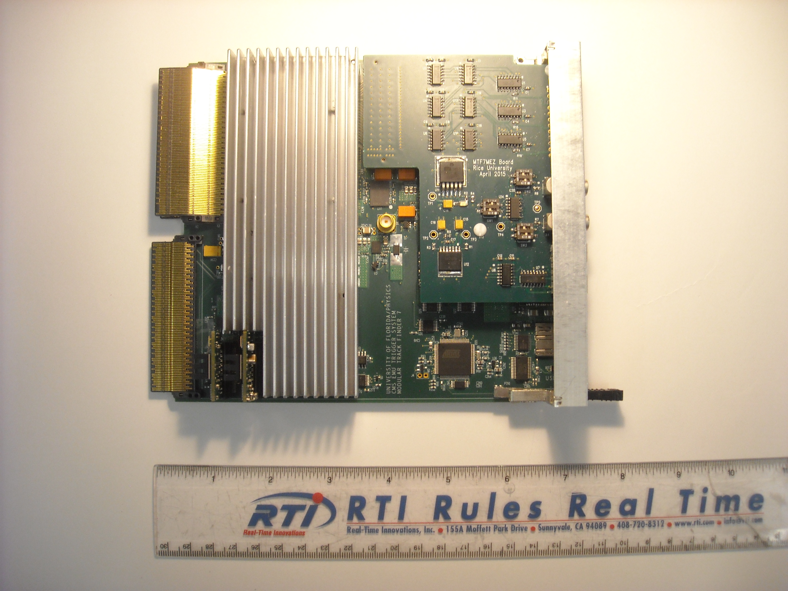
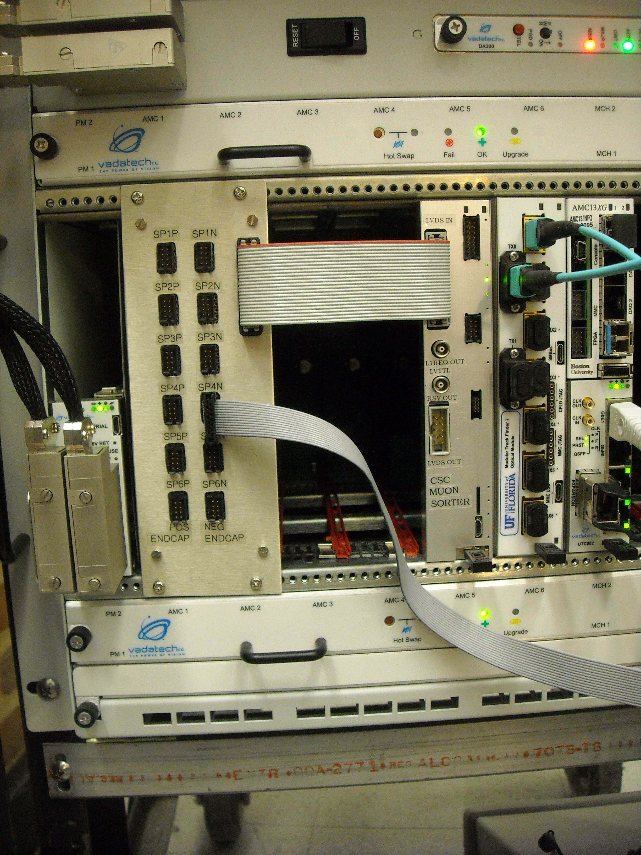
Mezzanine Board for the MTF7 Muon Track Finder
Production Version, February 2016

Production Version, November 2013

-
Most recent (2021) OTMB-to-MPC and MPC-to-EMTF data formats
-
MPC Mezzanine Specification ver.2.1 23 June 2020 (updated format)
-
MPC Mezzanine Specification ver.1.11. 5 May, 2018
- [TRIAL VERSION 17 June 2022] mcs configuration files for the XCF32P devices
mcs EPROM1
and mcs EPROM2 and bit file
and compressed mcs file for EPROM1 and compressed bit file
and svf file and a compressed svf file and a zip project file;
Version 06/17/2022 (DateID=2CD1h). Based on version 07/23/2020. New feature: TMBi_HMT[j] (i=1..9; j=0..3) bits now propagate independently from LCTs.
- [TRIAL VERSION 23 July 2020] mcs configuration files for the XCF32P devices
mcs EPROM1
and mcs EPROM2 and bit file
and compressed mcs file for EPROM1 and compressed bit file
and svf file and a compressed svf file and a zip project file;
Version 07/23/2020 (DateID=28F7h). New 38B/40B encoding scheme for optical links. Latency reduced by 1BX. PRBS generators recovered on all links. GTP TX buffers enabled.
Draft software manual is available here.
- [TRIAL VERSION 17 July 2020, FOR TESTING PURPOSES ONLY] mcs configuration files for the XCF32P devices
mcs EPROM1
and mcs EPROM2 and bit file
and compressed mcs file for EPROM1 and compressed bit file
and svf file and a zip project file;
Version 07/17/2020 (DateID=28F1h). New 38B/40B encoding scheme for optical links. GTP TX buffers enabled.
Draft software manual is available here.
- [TRIAL VERSION 26 May 2020, FOR TESTING PURPOSES ONLY] mcs configuration files for the XCF32P devices
mcs EPROM1
and mcs EPROM2 and bit file
and svf file and a compressed project file;
Version 05/26/2020 (DateID=28BAh). New 38B/40B encoding scheme for optical links. GTP TX buffers enabled.
Draft software manual is available here.
- [TRIAL VERSION, FOR TESTING PURPOSES ONLY] mcs configuration files for the XCF32P devices
mcs EPROM1
and mcs EPROM2 and bit file
and svf file and a compressed project file;
Version 03/25/2020 (DateID=2879h), based on version 10/24/2017,
TMB1_LCT0_WG[6:0] in the 4th frame of GBT1 are swapped with the TMB1_LCT0_HS[6:0] in the 4th frame of GBT3
- [TRIAL VERSION] mcs configuration files for the XCF32P devices
mcs EPROM1
and mcs EPROM2
and svf file and a compressed project file;
Version 06/13/2018 (DateID=24CDh), based on version 05/05/2018,
increased (up to 16K) FIFO_B_NEW buffers (loaded upon arrival of the TTC BC0), new QPLL_LOCK counter,
100 millisecond long IDLE pattern + 100 ns BoardID to EMTF links on Hard Reset.
- [TRIAL VERSION] mcs configuration files for the XCF32P devices
mcs EPROM1
and mcs EPROM2
and svf file and a compressed project file;
Version 05/05/2018 (DateID=24A5h), based on version 10/24/2017,
increased (up to 16K) FIFO_B_NEW buffers (loaded upon arrival of the TTC BC0), new QPLL_LOCK counter.
- mcs configuration files for the XCF32P devices
mcs EPROM1
and mcs EPROM2
and svf file and a compressed project file;
Version 10/24/2017 (DateID=2358h), based on version 10/02/2016,
GTP TX buffer disabled, BC0 counters added for all 9 TMBs (available for read from
addresses 6000D2h (TMB1), 6000D4h (TMB2)... 6000E2h (TMB9), reset by RESYNC); simplified frame multiplexing to GTPs.
- mcs configuration files for the XCF32P devices
mcs EPROM1
and mcs EPROM2
and svf file and a compressed project file;
Version 11/28/2017 (DateID=237Ch), based on version 10/23/2016,
GTP TX buffer enabled, BC0 counters added for all 9 TMBs (available for read from
addresses 6000D2h (TMB1), 6000D4h (TMB2)... 6000E2h (TMB9), reset by RESYNC, minor changes
in clock distribution w.r.t. ver 10/23/2017).
- mcs configuration files for the XCF32P devices
mcs EPROM1
and mcs EPROM2
and svf file;
Version 10/23/2017 (DateID=2357h), based on version 11/31/2016,
GTP TX buffer enabled, BC0 counters added for all 9 TMBs (available for read from
addresses 6000D2h (TMB1), 6000D4h (TMB2)... 6000E2h (TMB9), reset by RESYNC).
- mcs configuration files for the XCF32P devices
mcs EPROM1
and mcs EPROM2
and svf file;
Version 10/02/2017 (DateID=2342h), based on version 11/30/2016,
minor changes in the BC0 path; BC0 counters added for all 9 TMBs (available for read only from
addresses 6000D2h (TMB1), 6000D4h (TMB2)... 6000E2h (TMB9)).
- mcs configuration files for the XCF32P devices
mcs EPROM1
and mcs EPROM2
and svf file;
Version 11/30/2016 (DateID=217eh), based on version 10/17/2016,
TX buffer disabled, tighter timing, improved GTP initialization, supports TMB-to-MPC data transmission tests for new links.
- mcs configuration files for the XCF32P devices
mcs EPROM1
and mcs EPROM2
and svf file;
Version 11/31/2016 (DateID=217fh), based on version 10/18/2016,
TX buffer enabled, tighter timing, supports TMB-to-MPC data transmission test for new links.
- mcs configuration files for the XCF32P devices
mcs EPROM1
and mcs EPROM2
and svf file;
Version 10/18/2016 (DateID=2152h), based on version 07/06/2016,
TX buffer enabled, tighter timing.
- mcs configuration files for the XCF32P devices
mcs EPROM1
and mcs EPROM2
and svf file;
Version 10/17/2016 (DateID=2151h), based on version 07/06/2016,
TX buffer disabled, tighter timing, improved GTP initialization.
- mcs configuration files for the XCF32P devices
mcs EPROM1
and mcs EPROM2
and svf file;
Version 07/06/2016 (DateID=20E6h), based on version 11/18/2014,
TMB1_LCT0_BC0 bit is transmitted in frame 2, line[13] of all 8 optical links.
Archived version is here.
- mcs configuration files for the XCF32P devices
mcs EPROM1
and mcs EPROM2
and svf file;
Version 11/18/2014 (Pre-production) (DateID=1D72h), based on version 09/22/2014,
TXENPMAPHASEALIGN=1, TX buffer disabled, VME access counter added.
- mcs configuration files for the XCF32P devices
mcs EPROM1
and mcs EPROM2 ;
Version 12/14/2015 (Trial) (DateID=1F8Dh), based on version 11/18/2014,
Intended for latency measurements. TP15 is connected to bit D(11) of the
GTP link 1 input (MGTTX0_101); it includes the TMB2_LCT1_VPF bit.
- mcs configuration files for the XCF32P devices
mcs EPROM1
and mcs EPROM2
and svf file;
Version 11/30/2015 (Trial) (DateID=1F7Eh), based on version 11/18/2014,
Nine BC0 counters added for LCT0 from TMB1-TMB9; available for read from addresses base+d2, base+d4... base+e2.
- mcs configuration files for the XCF32P devices
mcs EPROM1 uncompressed
and mcs EPROM2 uncompressed
and svf file;
Version 09/11/2014 (Trial) (DateID=1D2Bh), based on version 08/22/2014, IDLE generation
has been modified, default reset of GTPs added, access to AFBR-810 internal registers added.
- mcs configuration files for the XCF32P devices
mcs EPROM1 uncompressed
and mcs EPROM2 uncompressed
and svf file;
Version 08/22/2014 (DateID=1D16h), based on version 08/21/2014, but resynch procedure is
similar for both new and old optical links.
-
MPC Mezzanine Draft Specification 1.8. 9 April, 2014
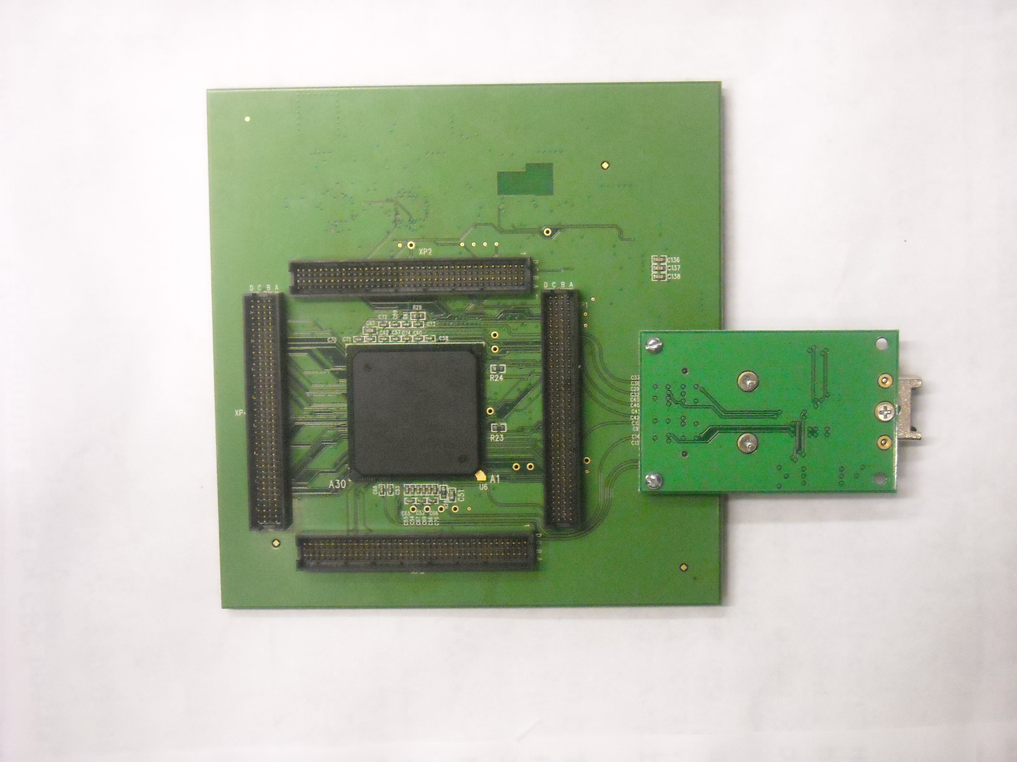
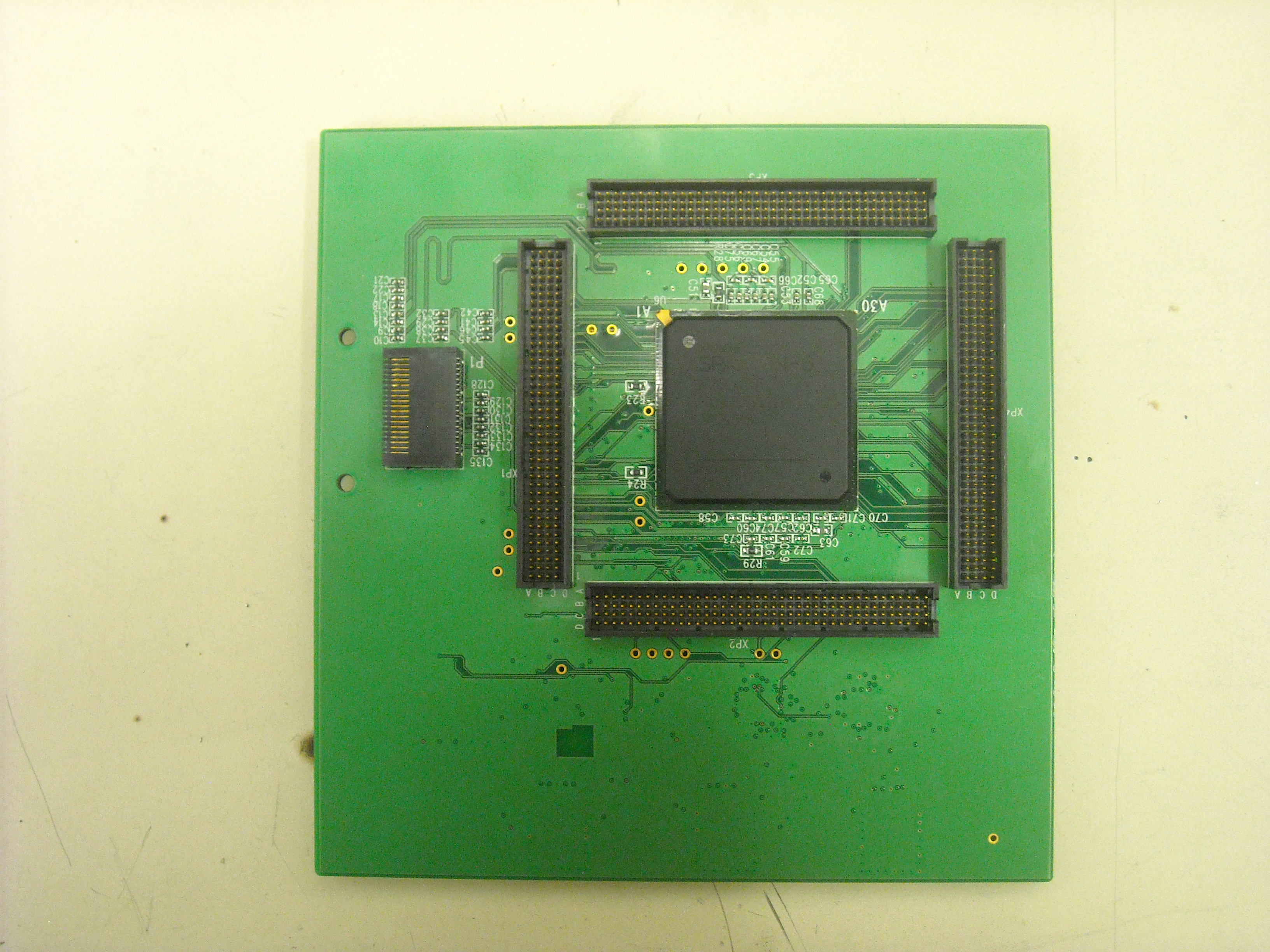
- Spartan-6 Mezzanine Ver.2 Schematics (pdf files)
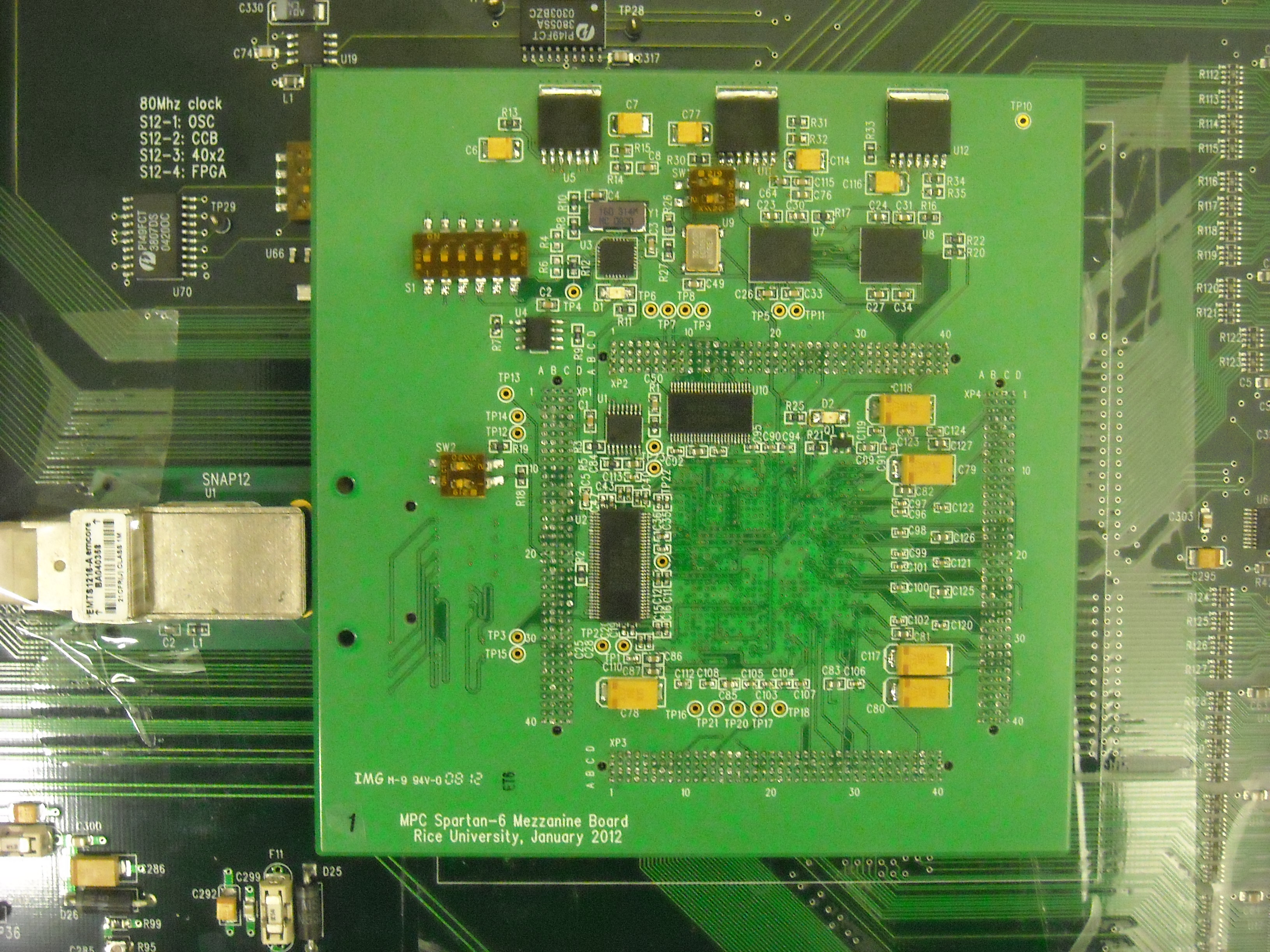
First Revision, April 2012
-
MPC Mezzanine Draft Specification 1.5. 15 May, 2012
- Configuration files (.mcs) for the XCF32P devices
EPROM1
and EPROM2 Version 05/16/2012 (DateID=18B0h)
(TX buffer disabled, IDLE pattern added, adjustable clock to GTPs, GTP RX error counters added).
-
MPC Mezzanine Draft Specification 1.2. 13 April, 2012
- Configuration files (.mcs) for the XCF32P devices
EPROM1
and EPROM2 Version 04/13/2012 (DateID=188Dh)
(TX buffer enabled, IDLE pattern added).
- Configuration files (.mcs) for the XCF32P devices
EPROM1
and EPROM2 Version 04/13/2012 (DateID=188Dh)
(TX buffer disabled, IDLE pattern added).
-
Instruction for the Irradiation Test, 9 May, 2012
and ISE 13.4 Project.
- Uncompressed configuration files (.mcs) for the irradiation test
EPROM1
and EPROM2 Version 05/08/2012
- Compressed configuration file (.mcs) for the irradiation test
EPROM1.
Version 05/08/2012
- Spartan-6 Mezzanine Schematics (pdf files)
- FPGA/EPROM configuration and GTP links
- clock distribution
- mezzanine connectors
- FPGA input/outputs
- power distribution
- pluggable SNAP12 optical transmitter
Optical DMB Test Project
Second Revision, March 2013
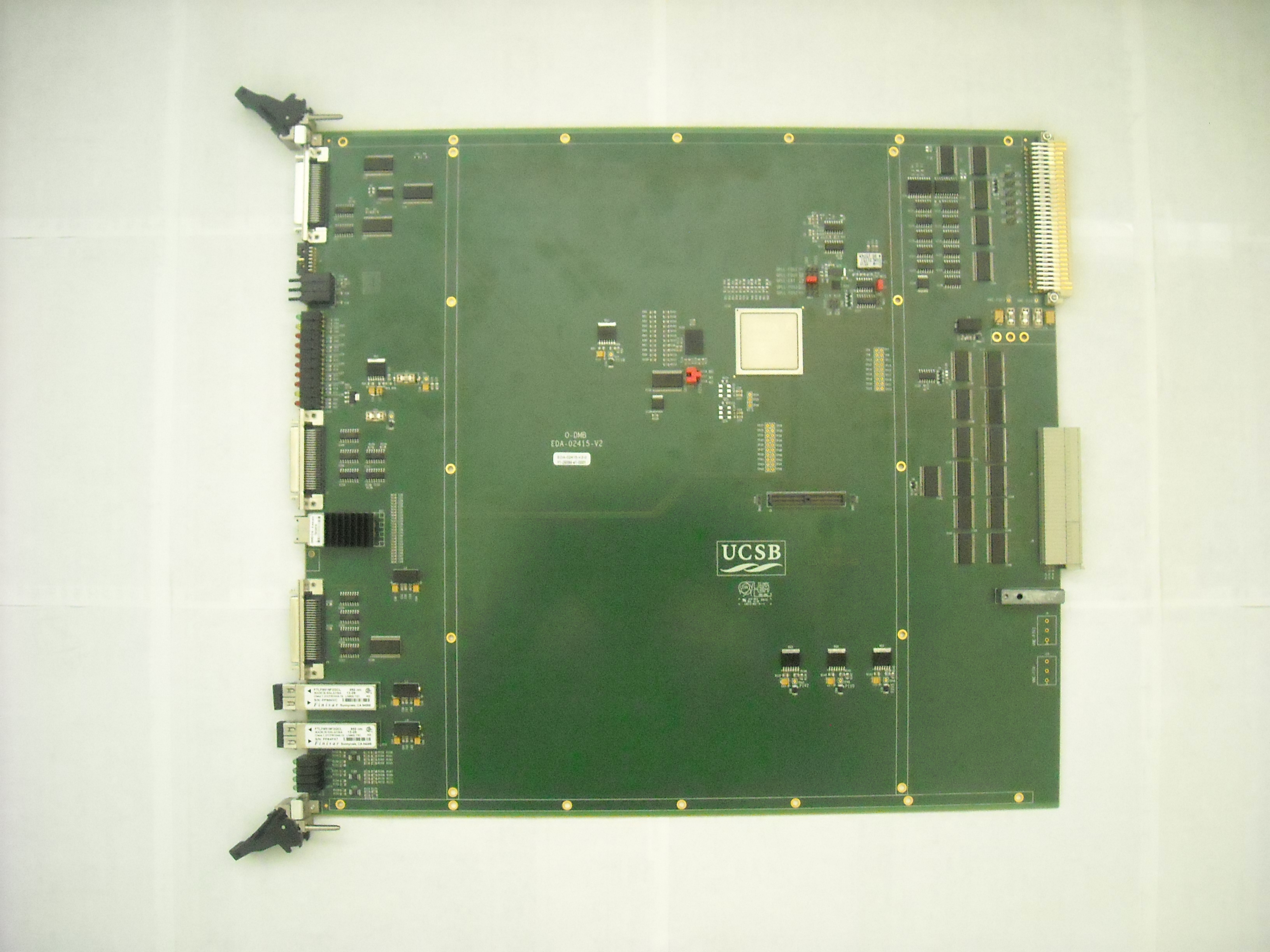
-
DCFEB Optical Test Stand (User's Guide, August 2018).
Configuration bit file for the DCFEB FPGA.
Configuration mcs file for the ODMB XCF128X PROM.
-
Firmware Reference Manual, 22 June 2018
and a
configuration mcs file for the
XCF128X EPROM, 22 June 2018 (for ODMB v.2, some test points added)
-
Firmware Reference Manual, 8 September 2016
and a
configuration mcs file for the
XCF128X EPROM, 8 September 2016 (for ODMB v.3&4, some register changes)
- Configuration files (.mcs and .bit) for the
XCF128X EPROM and the
V6 FPGA, 22 June 2018 (similar to version 4 August 2016,
for ODMB v.2)
-
Firmware Reference Manual, 10 May 2013
- Configuration files (.mcs and .bit) for the
XCF128X EPROM and the
V6 FPGA, 30 August 2016 (similar to version of 24 August 2016,
for ODMB v.3&4, V6_JTAG_SEL=1 permanently)
- Configuration files (.mcs and .bit) for the
XCF128X EPROM and the
V6 FPGA, 24 August 2016 (similar to version of 4 August 2016, but compiled for ODMB v.3&4)
- Configuration files (.mcs and .bit) for the
XCF128X EPROM and the
V6 FPGA, for ODMB ver.2, 4 August 2016 (can capture data on L1RES signal)
- Configuration file (.mcs) for the XCF128X
EPROM, 19 December 2013 (optimized for
optical tests with the MPC board)
- Configuration file (.mcs) for the XCF128X
EPROM, 10 May 2013 (TMS to DCFEB is sourced by pin AJ10,
TDI to DCFEB is sourced by pin AK11; continuous generation of all PPIB signals added)
- Configuration file (.bit) for the XC6VLX130T
FPGA, 10 May 2013 (TMS to DCFEB is sourced by pin AJ10,
TDI to DCFEB is sourced by pin AK11; continuous generation of all PPIB signals added)
- Configuration file (.mcs) for the XCF128X
EPROM, 9 May 2013 (TMS to DCFEB is sourced by pin AJ10,
TDI to DCFEB is sourced by pin AK11)
- Configuration file (.bit) for the XC6VLX130T
FPGA, 9 May 2013 (TMS to DCFEB is sourced by pin AJ10,
TDI to DCFEB is sourced by pin AK11)
- Configuration file (.mcs) for the XCF128X
EPROM, 17 April 2013
- Configuration file (.bit) for the XC6VLX130T
FPGA, 17 April 2013
- ODMB ver.2 schematic design
pdf file, March 2013
First Revision, March 2012
-
PCB modifications, 13 December 2012
-
Firmware Reference Manual, 6 December 2012
- Configuration file (.mcs) for the XCF128X
EPROM, 7 December 2012
- Configuration file (.bit) for the XC6VLX130T
FPGA, 7 December 2012
- Code to program/readout the LVMB
txt, December 2012
- Xilinx ISE 13.4 test project
zip file, 7 December 2012
Avago12-SNAP12 Adapter Board
This board was built in spring of 2017 and intended for evaluation of the
Avago AFBR-820 12-channel optical receiver
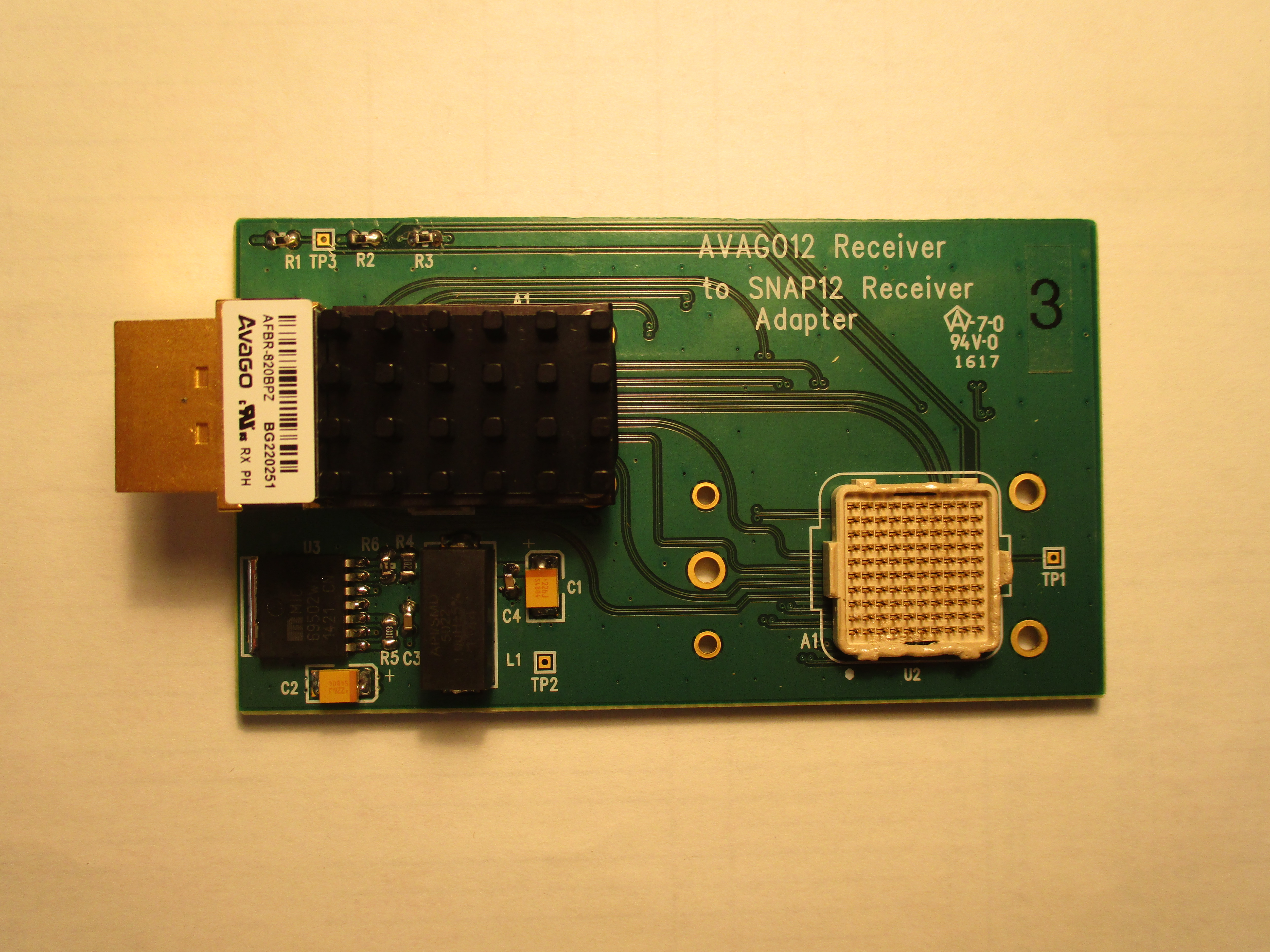
Adapter Board schematic, 10 April 2017
Samtec FireFly-SNAP12 Adapter Board
This board was built in spring of 2017 and intended for evaluation of the
Samtec Firefly 12-channel optical receiver
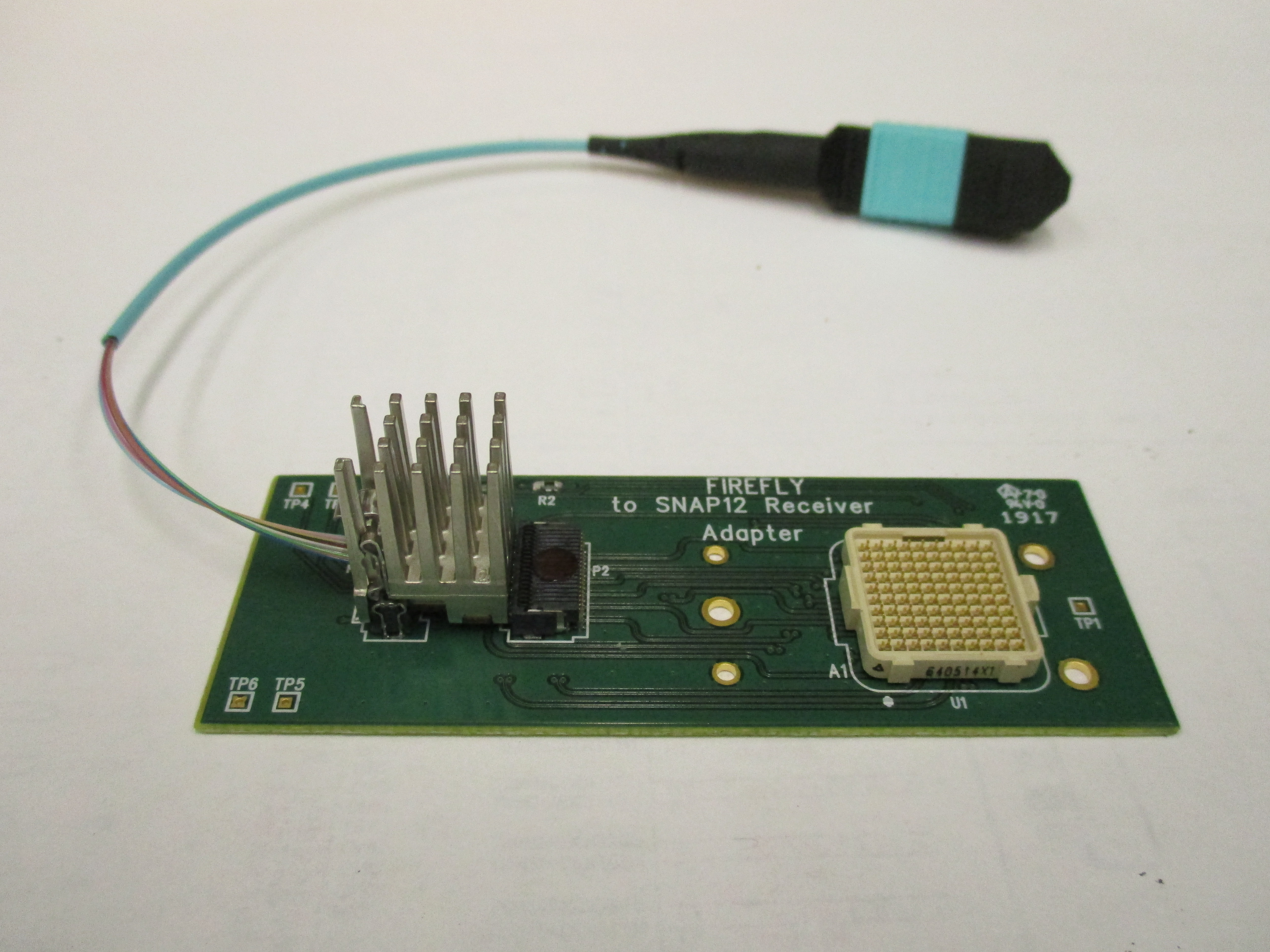
Adapter Board schematic, 17 April 2017
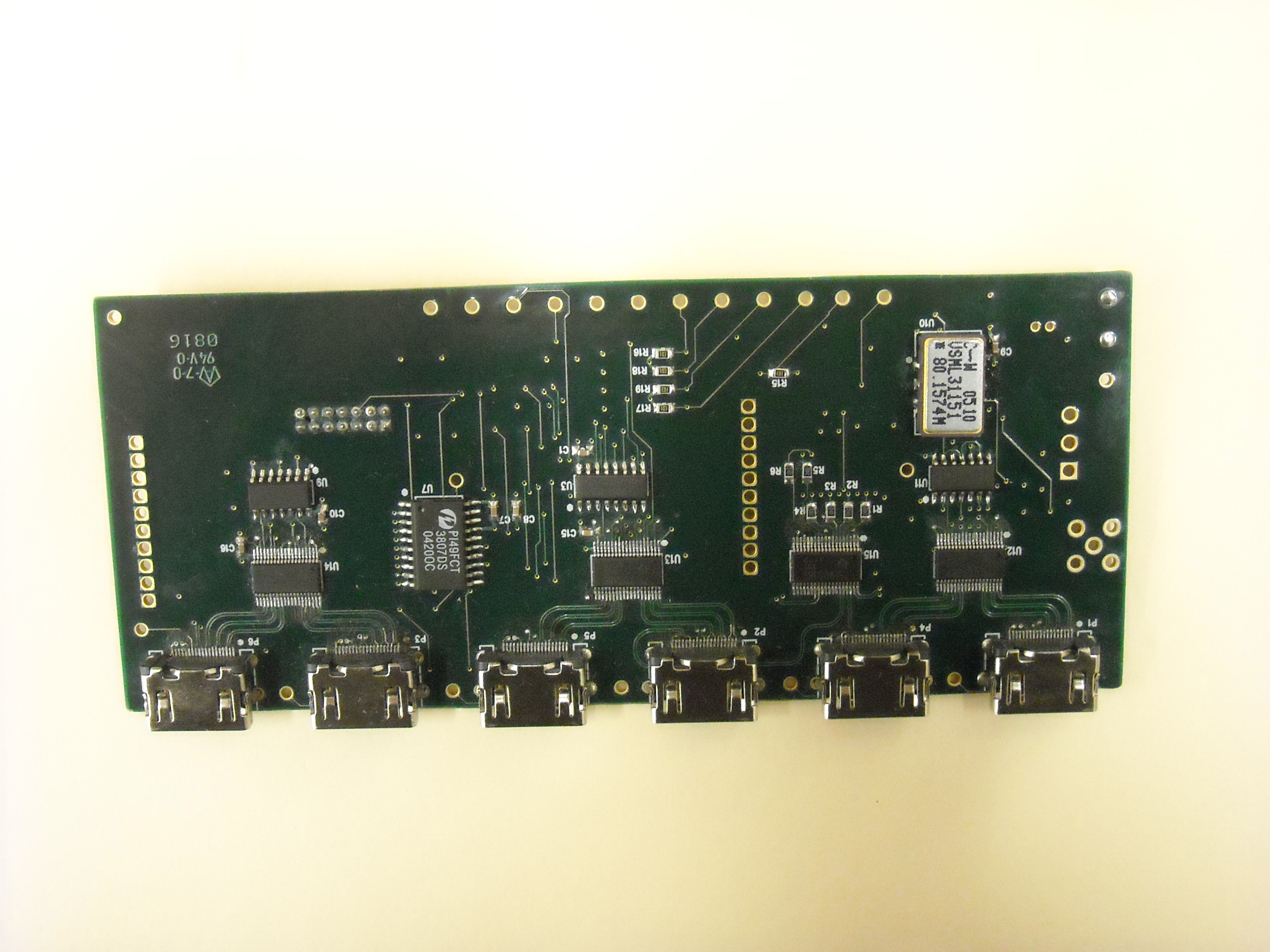
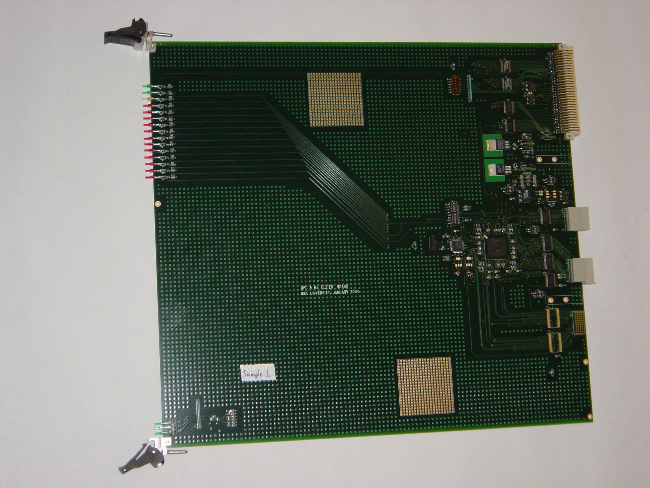
Muon Tester Board
Muon Tester board is intended for testing of the CCB, MPC and MS boards.
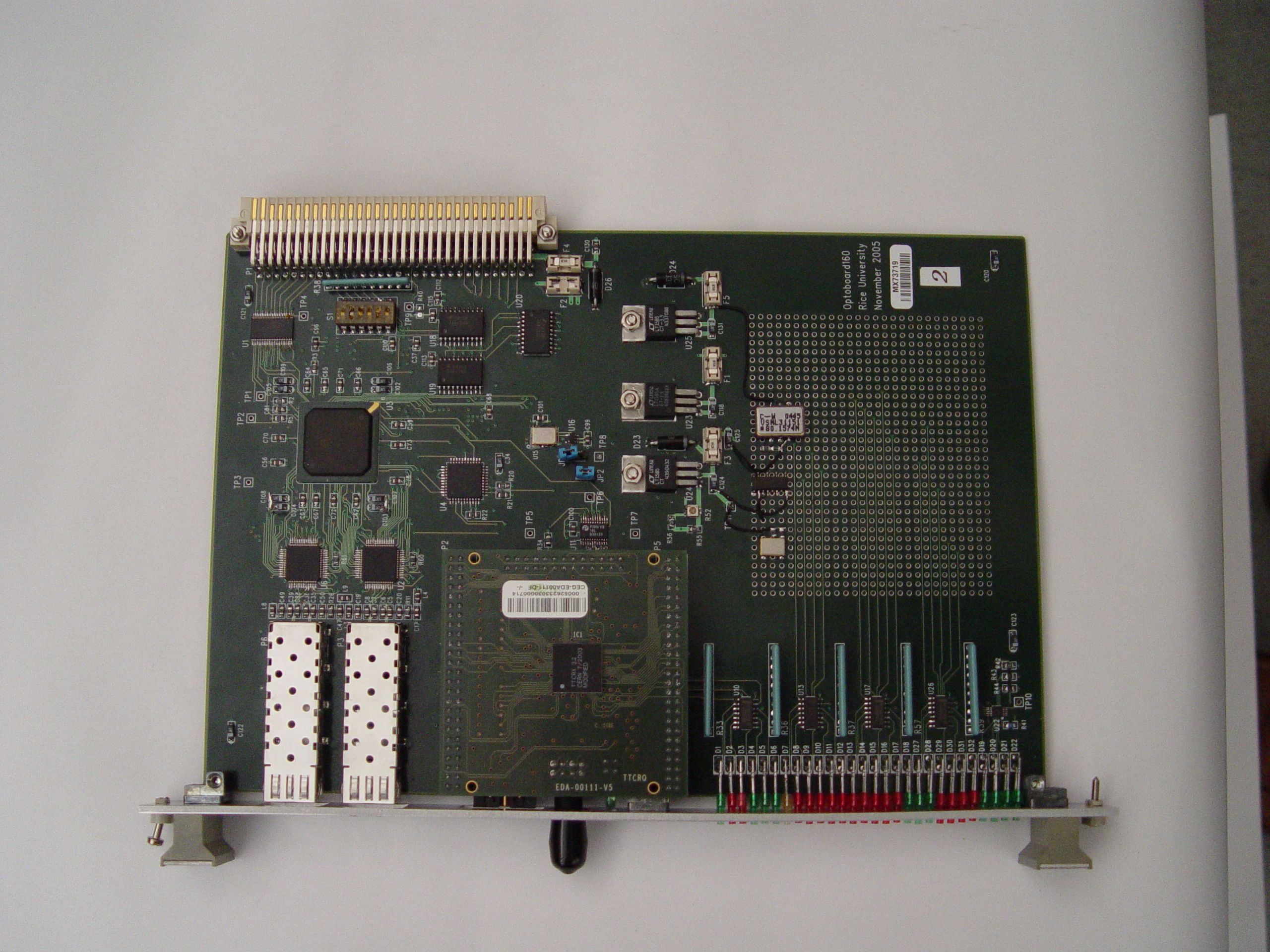
Optoboard160
This board was built in the fall of 2005 and intended for evaluation of the
Texas Instruments TLK3101 gigabit transceivers and Finisar FTRJ8524
optical modules operating at 160MHz.
Evaluation Optoboard
This board was built in spring 2001 and intended for evaluation of the
Texas Instruments TLK2501 gigabit transceivers and Finisar FTRJ-8519
optical modules.
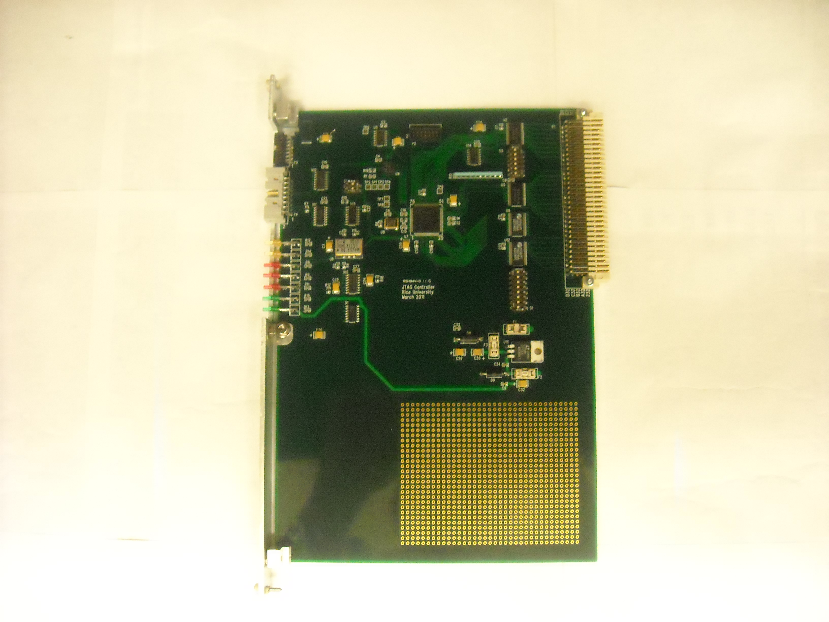
JTAG Evaluation Board
This board was built in spring of 2011 for evaluation of the
National Semiconductor SCANSTA101 JTAG Master.